Superconductivity
For the Superconductivity review see the QCMP notes
Relevant formulas
Artificial atom
One of the possible ways to create qubits is to draw inspiration from nature and build a devices that behaves similarly to atoms, which have the following properties:
- Have sharp energy levels
- Have different separation between the levels
- The internal state can be controlled by shining on the atom a laser with a specific wavelength
- Have long decay and coherence time
The idea to create an artificial atom is to arrange standard superconductive circuit elements (inductors, capacitors, etc.) in order to obtain the desired properties.
LC resonator
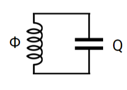 The simplest device we can build is an LC resonator like the one in the picture above. Its potential and energy levels are the following ones:
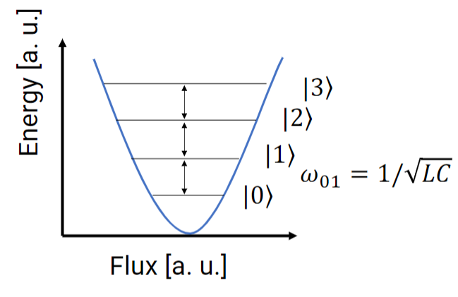
In principle, the initialization of this system in the ground state is relatively simple, because with current fabrication techniques we can design properly L and C to have a resonant frequency of
This means that, in theory, this device could be operated at a temperature
In conclusion ==the LC resonator cannot be used as a qubit==.
Before proceeding to solve this issue it is useful to find the Hamiltonian of the LC resonator because it will be useful later.
Hamiltonian of the LC resonator
Similarly to the classical case of the harmonic oscillator (mass and spring or ball in a cup), the Hamiltonian of the LC resonator can be written as the sum of two terms that resemble the kinetic and potential energy:
To find the value of
We can proceed by summing and subtracting
With
We can now substitute the values inside
Superconductive qubit
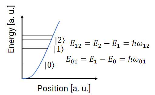
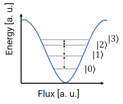
Instead of using a simple inductor, which gave rise to an harmonic potential (i.e. equally spaced energy levels), we can replace it with a Josephson Junction, which, according to
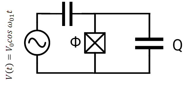
With this change we introduce some anharmonicity in the potential, with the wanted effect of obtaining different spacing between the various energy levels.
Hamiltonian of the SC qubit
To find the Hamiltonian of the qubit we need to find the expression of the (potential) which can be done using
with
Similarly to before, the Hamiltonian will be:
where
For the time being we can limit our study to the case where the AC voltage generator is off and so we remove it from the circuit. We also have to consider the fact, that due to defects in the materials, and noise, even with no applied voltage, there will be a certain potential
The perturbation induced by the
To account for this we slightly change the Hamiltonian as follows:
Choice of
To reduce the effect of the noise we can tweak the values of
If
![]()
It is easy to see that in this case we have a very high anharmonicity but, at the same time, we have a very high sensibility to variation of
Increasing the ratio
![]()
We can see that this case has the same problem of being very sensitive to variations of
Even so, we notice that the amplitudes of the fluctuations of the energy levels are reduced.
If we keep increasing the ratio
![]()
To further increase the ratio we need to increase the capacitance of the capacitor (since
![]()
If we plot the charge dispersion the amplitude of the oscillations in the energy levels) as a function of the ratio
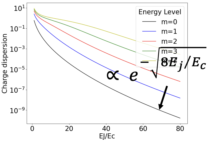
we observe that the dispersion associated with the different energy levels have a dependence that goes like:
We can also plot the relative anharmonicity (difference of the splitting of the energy levels with respect to the case of equally spaced energy levels) as a function of
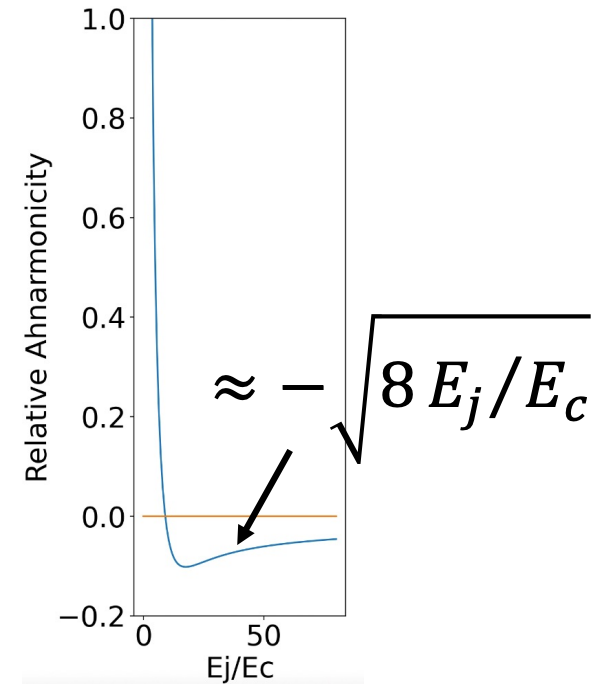
The dispersion is way screened faster than the anharmonicity (exponential vs square root function). This is what allows to reach a scenario where the qubit is largely insensitive to charge noise, while retaining a sufficient anharmonicity.
Transmon regime approximations
Neglect
When operating in the transmon regime we can neglect the contribution of
Taylor expansion
Since when working with qubits we are interested in the first two energy levels only, we can restrict our study to the bottom of the “valley”, where the contribution of the cosine is negligible. Keeping this in mind and performing a Taylor expansion, we get
(in the second step we just assigned new names to the constants).
In this case (JJ instead of Inductor) we have a “corrected” Harmonic oscillator or a “weakly anharmonic oscillator”.
Ladder operators
From the definitions of the ladder operators (which in this case we call
which allows us to rewrite the first two term of the Hamiltonian as
The term
On the other hand, can be demonstrated that the anharmonic part of the Hamiltonian (highlighted in red within the formula) can be effectively reformulated using the Rotating-Wave Approximation (RWA). Within this approximation, terms within the Hamiltonian characterized by an unequal number of creation (
The validity of the Rotating-Wave Approximation hinges on the assumption that terms with unequal numbers of annihilation and creation operators lead to rapid oscillations. This assumption holds true when the energy associated with the qubit (
So if we factor out
Where
What we end up with is the following:
![]() The second term in the Hamiltonian gives NON-LINEARITY to the system and brings to the fact that the first transition frequency is larger than the second one, with a shift given by
The second term in the Hamiltonian gives NON-LINEARITY to the system and brings to the fact that the first transition frequency is larger than the second one, with a shift given by
Coherent Control of Qubits
To implement a logic gate effectively, it’s imperative to understand the dynamics of our qubit within the transmon regime. In this regime, external charges cease to perturb the qubit, simplifying our study to focus solely on the internal dynamics.
When subjecting our qubit to an RF signal at the appropriate frequency (the transition
The analysis of real-world measurements reveals a crucial relationship between pulse width (in ns) and error per gate (EPG).
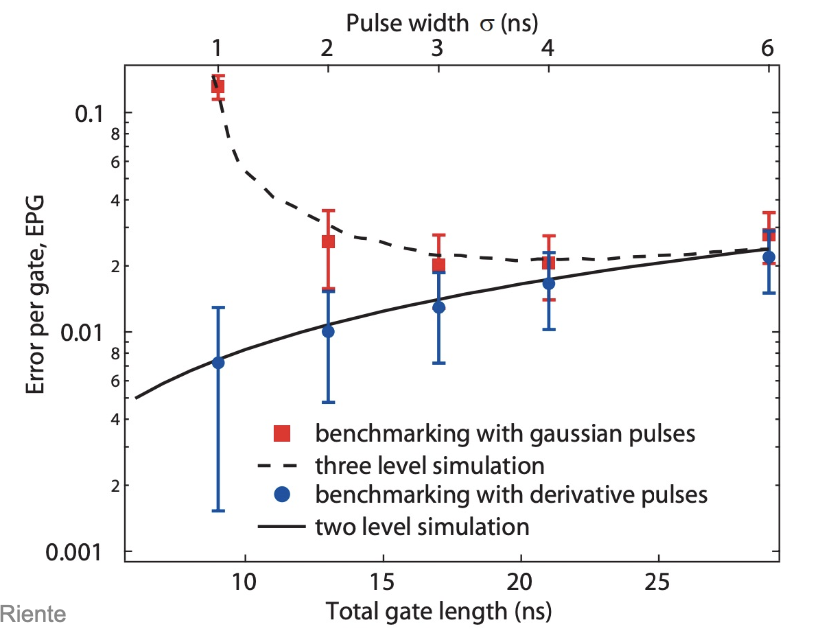
Observations indicate that upon reducing the pulse width, we see an INCREASE in the ERRORS, due to leakage. This is because when we reduce the pulse width applied to the circuit, we have sharper edges in the signal, so higher BAND in the frequency.
Moreover, as pulse duration increases, error per gate becomes predominantly influenced by relaxation and dephasing effects, indicative of decoherence phenomena.
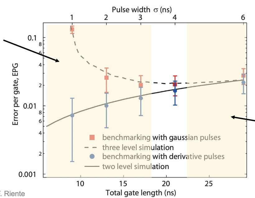
In essence, challenges associated with low pulse widths stem from finite anharmonicity, while those at high pulse widths are attributed to relaxation and dephasing effects. Therefore, optimal control necessitates pulse shaping to minimize leakage and operate within the designated “white region” highlighted in the analysis.
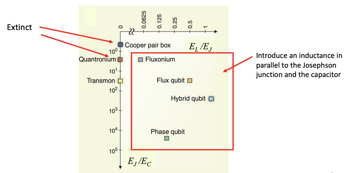
Additional Insight: It’s worth noting that the transmon isn’t the sole superconducting qubit option available. Other alternatives, such as quantronium and the Cooper pair box, although now obsolete, have been explored. These implementations often introduce parallel inductors to facilitate further tuning and unique effects, broadening the spectrum of available options for qubit control and manipulation.